This is the new web site for our project called Bench Jet Engines.The purpose of the site is to demonstrate that a model jet engine can be made quite simply with the minimum of materials and using basic design ideas.Along with a friend of mine Magnus,who got me (Mick) in to all of this we decided in April 2001 after seeing a schematic in an old book to copy it almost literally,luckily we work in a well equipped engineering works so the necessary machines and materials were readily available.
Below is the first drawing of our jet engine. Although it is a schematic the finished version will also look very much like this and yes we are using a blow lamp for our heat source!
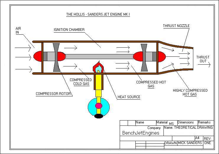
SCHEMATIC DIAGRAM
So far we have made the body and the rest of the bits including the rotors although some filing is due to make the rotor blades more aero dynamic basing the blade shape on an aircraft wing for efficient air flow(unfortunately this takes some time-about half an hour per blade!).We bought the bearings from a skateboard shop@�2.50 each-well cheap and can run at fairly high temperatures although the engine has not been run yet so we don't know if they will be suitable or seize up as oil fed bearings will not feature on this basic prototype-hopefully they will on the MK.II engine though. A predicted speed of about 30,000 RPM is what we hope the engine running speed will be at least,with a starting speed of about 2,000 RPM or higher which brings me nicely on to the starting system which is an old gas bottle charged with compressed air and released by a valve through a small nozzle drilled into the side of the engine in line with the compressor rotor.
We had a basic design dilemma early on which was the absence of compression between the front rotor and the rear rotor which was solved by a tapered bush fitted on the drive shaft tapering from the front rotor to the rear,hopefully this will solve the problem.
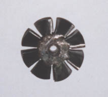
Shown here is one of the rotors nearing completion,a bit more filing and it should spin like the clappers.The rotors have taken the most amount of time to do so we hope they work well.Most of the material used in the engines construction is mild steel as this is a prototype and experimental jet engine-the MK.II will be made mainly off stainless as it will withstand higher temperatures better and also looks more pleasing to the eye,i.e. nice and shiny.As we are only using a blow lamp for the heat source metal distortion should not be a problem on the MK.I.
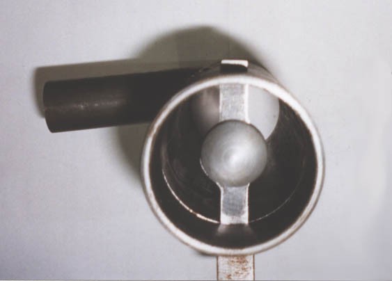
This photo shows the end on view of the engine.Air enters this end so the center strut supporting the bearing assembly has a cone on it to help smooth the air flow.The cone was made on a small lathe and was not turned to any exact dimensions,just a nice cone shape and very smooth.
The other end is similar looking but with an inwardly tapered cone on the center strut to enable the hot air to exit smoothly with the least air resistance,as the rear nozzle is tapered to a smaller diameter.The cone was also made to no particular measurements,but looked to be about the right shape and size.Inspiration for the end cones was from observations of full size jet engines so I thought I'd put some on the MK.I.
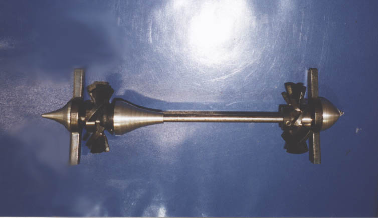
A nice picture of the semi-completed rotor assembly,roughly lined up to show the finished layout.Most of the components are shown here although they have to be finish machined yet.The cone shaped piece is the compressor cone,quite roughly machined at the moment but it should work ok for the prototype.The rotors and the compressor cone are all held in place by grub screws.
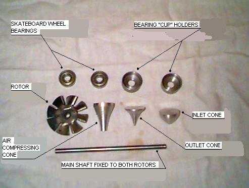 Here are some of the internal components,we've used standard skateboard bearings-although ceramic ones were available @�6.50 each-we might have to use the latter as they suit higher temperatures.It's possible that these bearings will seize in the heat-especially the exhaust one,so the first runs will be short ones and hopefully successful although if the motor does seize on the first run at least it would be excellent!
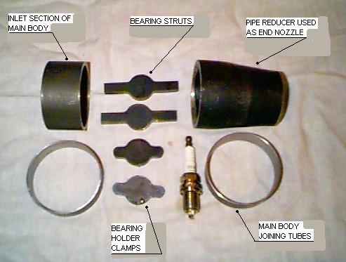 More components....considering that this thing should spin like mad and produce some thrust,the amount of the components is very small compared to,say,a petrol engine,in fact when I look at the motor theory behind the jet engine it seems too simple to work as well as it does.It shows that a simple design can most of the time be the best,woffle woffle....
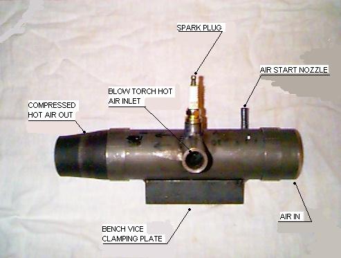 A side view of the nearly completed engine-a bit chunky but it is a prototype....note the air start tube sticking out near the top by the inlet end,this is for the air start as the motor needs a kick start of a couple of thousand RPM to get it going. It was originally planned to start the motor with the compressed gas from a hand held air horn but we read the label on the cannister and realized that it had flammable gas in it,a nice small explosion if we switched the spark plug on! The starter now is going to be a small gas bottle with a couple of valves on charged with compressed air which should give us the pressure we need to get it going.
11/9/2001..At last the engine is assembled and ready to fire up! We spun the engine up to a few thousand revs. using an airline and as a makeshift heat source used a hot air gun which produces 600 oC..hot enough..but the engine (boo hoo) didn't catch. Two things were on the start up:
1/ The engine vibrated,probably due to the rotors being out of balance at high-ish revs,and
2/ There was some end float on the shaft.
Once these problems have been fixed,we should have some better results,i.e. it should run.Also,a friend suggested that the heat source might work better being a flame as the gasses inside the body might expand quicker drawing more air in from the velocity stack(the "air In" tube )and there bye spinning the front rotor faster,also the hot air gun pushed additional air in from the flame inlet tube at the side of the motor,we're not sure if the extra air is good so I'm rapidly building the ignition circuit up at work in my dinner-breaks,roll on the next test!
8/10/2001 No luck with the Sparking Circuit so far,we'll try a lawn mower spark plug as the present plugs don't have a strong enough spark,failing that a model aeroplane glow plug may do-although we suspect that it might burn out after a short time. On the positive side-the final shaping of the rotors is well under way and the vibration problem seems to be cured as the rotors and shaft are in a better state of balance.

And here is a picture of two dodgy looking people..AKA Mick and Magnus,the accredited designers and builders of the Hollis-Sanders jet engine.
12/November,2001...
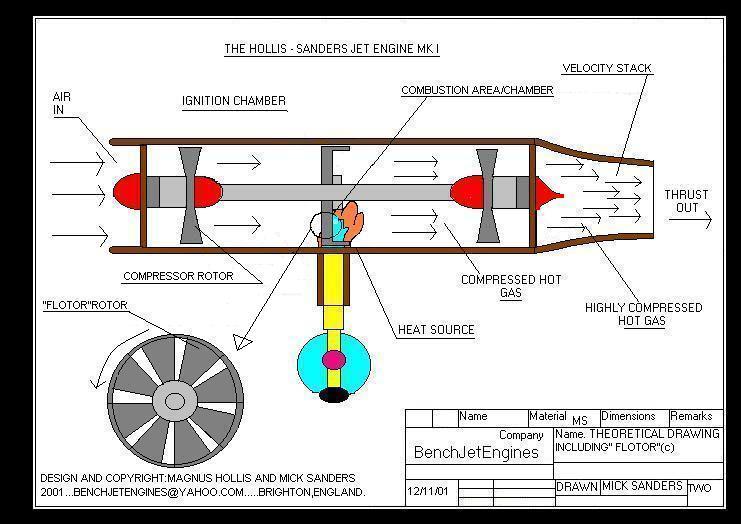
A new piece to the engine has been designed by Magnus,a prototype ROTARY FLAME CATCHER!.The theory behind the catcher is simple,as the flame enters the combustion area it gets trapped within the rotating blades due to the blades being bent at an angle of 90 degrees to the axis of the engines' spindle.This ensures theoretically that the flames are "caught"within the flame trapping rotor-or "Flotor"as I have just decided to call it-and as the outer Flotor fins are joined to the engines spindle by "normal"fins-the Flotor shouldn't resist the jets' airflow too much and the result should be that the flame does not get blown out or "flame out" as it is called.The benefits of the rotary flame catching outweigh the small amount of increased air turbulence that the Flotor will induce.The drawing below is a schematic to show where the Flotor will be in the finished engine.The Flotor will be made of-initially-tin plate,actually a Heinz baked bean tin lid as it is thin steel and was kicking around at the time.If the Flotor works then a more robust one will be built from thicker gauge steel.Photos to follow soon...
Neil,a friend at work and an avid vintage bus enthusiast is trying to source a bus turbocharger for the MK II engine,the bigger the turbo the better,this will then be stripped and the two rotors and the spindle plus the oil cooled bearings will be used on the new motor.Will the MK I ever be up and running before then you may well wonder,the answer is a definite yes! Job commitments have slowed the project down a bit but it is still going ahead.The rotor blades are still being filed into aerodynamic shapes and we are still working on an alternative ignition circuit as the first one produced too weak a spark and kept extinguishing the flame.
21 november,2001The problem with the spark circuit has been solved at last.Our new approach will be to use the age old system of a distributer(modified heavilly).The idea is to remove the distributor cap and fit a 12v windscreen wiper motor to the cog end of the unit,spin the shaft and use the existing points with the HT coil,this will give us a fairley constant spark.The dwell angle and points gap can still be adjusted so we can fiddle about a bit and get a good spark.The old transistoriseed ignition circuit has been binned(good riddance) and were back to basics.So its off to the scrap yard this weekend-a fiver should do it-and hello fat,bright sparks that do not get blown out by the gas preassure of a cigarette lighter!A jig to hold the motor and distributor together is easy to build,the power supply for the motor will be a car battery for mobility.The emptying of the gas bottle which will be our air-start reservoir will take place this weekend so we can crack on and fit the new valve assy. to the top of the bottle and weld an adaptor on for the charging up of the cylinder.
Below is a photo of one of the first engines made and designed by Sir Frank Whittle in 1937,hats off to that man!!
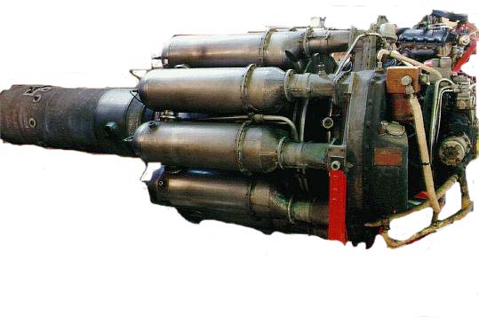
A nice piece of engineering....
17/06/2001..
Here is a picture of a phantom jet breaking the sound barrier and that is the sound wave that you can see.The picture came from a good web site connected with model jet engines but I can't remember who's it is otherwise I would credit this excellent photo.
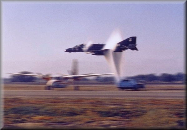
PHANTOM JET BREAKING THE SOUND BARRIER AT 60 FEET!
This site is still under construction,so watch this space!
Comments?Click on HERE to E-Mail us....
LINKS TO OTHER SITES :
- NYE THERMODYNAMICS---Check out the video clip -mad stuff!
COOL STUFF
A BEUTIFULLY ENGINEERED THROUGH FLOW COMBUSTION CHAMBER TURBO CHARGER JET ENGINE
MY NEW Steampunk JET ENGINE WEBSITE!

CREDITS AND THANKS TO:Magnus,Jackie,Cath,Ray,Mick,Neil,Charlie & Niall.


